 |
 |
 |
|
Fig.1 |
Fig.2 |
Fig.3 |
 |
 |
|
|
 |
|
Fig.4 |
Fig.5 |
Fig.6 |
Fig.7 |
Fig.8 |
 |
 |
 |
 |
 |
|
Fig.9 |
Fig.10/11 |
Fig.12/13 |
 |
|
 |
|
Fig.14 |
Fig.15 |
Fig.16 |
 |
 |
 |
 |
|
|
|
Fig.17 |
Fig.18 |
Fig.19 |
Fig.20 |
Fig.21 |
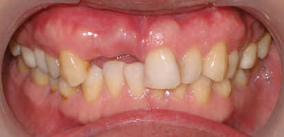
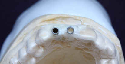
Attention to make stent for anterior implant
A 43 year-old lady has lost #7 and 8 due to caries for ~ 2 year. It
appears that the ridge is wide (Fig.1).
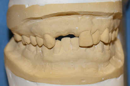
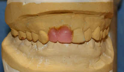
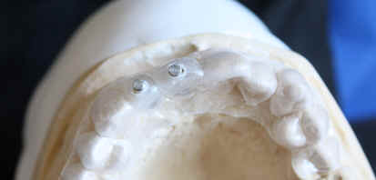
To place implants in ideal position, cone beam CT is planned. Models are
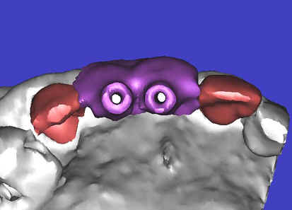
mounted (Fig.2); diagnostic wax-up is finished (Fig.3). Drill sleeves
(arrowheads in Fig.4; 10 mm long, 2.2 mm in diameter; Straumann) are placed
lingual to the incisal (I) edges of the neighboring teeth. The position of
drill sleeves is confirmed by CT: between the incisal edge and the cingulum
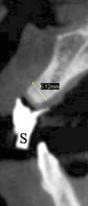
(Fig.5). The cross sections at #7, 8 and 9 are shown in Fig. 6, 7 and 8,
respectively. However, the long axis of the sleeve (S) or the natural
tooth #9 is not aligned with that of the alveolar ridge. This
orientation is good from prosthetic viewpoint, but we cannot place a long or
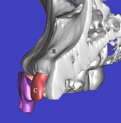
wide implant. The lateral view of the three-dimensional image shows
that the long axis of the crown (C) of #9 is not in line with that of its
root/ridge (R, Fig.9). It appears that the trajectory of an implant should
be not decided by wax-up, but should be adjusted to accommodate the morphology
of the
alveolar ridge. In all,
the drill sleeve (S) should be moved and tilted more labially to place the
longest and largest implant.
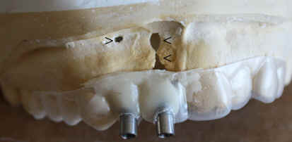
Back to model surgery (Fig. 10, upper panel), the osteotomy for #8 (pin from
Straumann) has been adjusted parallel to the surface of the alveolar ridge (R),
as compared to that of #7 of the previous design. Next, the incisal end of
#7 and 8 pins is labial to the incisal edge, instead of lingual to the latter
(Fig.11, lower panel). Finally the drill sleeves are positioned labial to
the incisal edge (Fig.12). The labial view also shows the point
(Fig.13). In addition, the model surgery allows the surgeon to experience
the perforation of the labial bone (apical fenestration defect, single arrowhead
and large dehiscence defect, double arrowheads) before a big day.
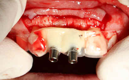
The adjusted stent fits well after raising the flap (Fig.14). Initial
osteotomy is made using the stent. The osteotomy for #8 is located in the
middle of the ridge labiolingually, whereas that for #7 is too lingual.
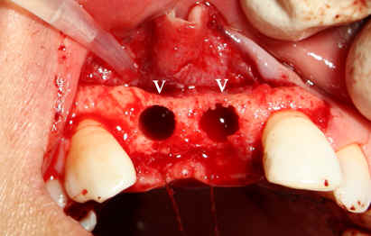
Adjustment is made freehand. The final osteotomy is shown in Fig.15: 4.0
mm in diameter for #7 and 4.5 mm for #8. With direct vision (large
exposure) and digital palpation, there is no perforation (not shown).
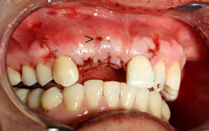
There is concavity in the labial plate (arrowheads in Fig.15), which is
corrected by connective tissue graft. The arrowhead in Fig.16 points to
the suture that stabilizes the graft against the labial mucoperiosteal flap.
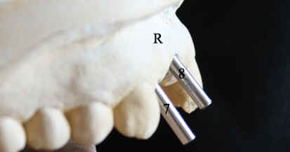
Fig.17 shows paralleling pins at 8 mm (trajectories are corrected
sequentially, but not enough); Fig.18,19: reamers 4.0 mm at #7 and 3.5 mm at #8
at the depth of 11mm; Fig.20 reamers 4.0 mm at #7 (14 mm deep) and 4.5 mm at #8
(11 mm); Fig.21: Bicon implants: 4.0 x 11 mm at #7 and 4.5 x 8 mm at #8.