 |
Fig.1 38 year-old male patient presented in
2006 with chief complaint "loose bridges". Exam shows poor
oral hygiene and restoration, and advanced periodontal disease.
Initial treatment includes removal of grossly nonsalvageables, scaling
& root planing, and upper removable partial using #1 as distal
abutment. Due to pneumatic sinuses and finance, implants would be placed in the
mandible first. |
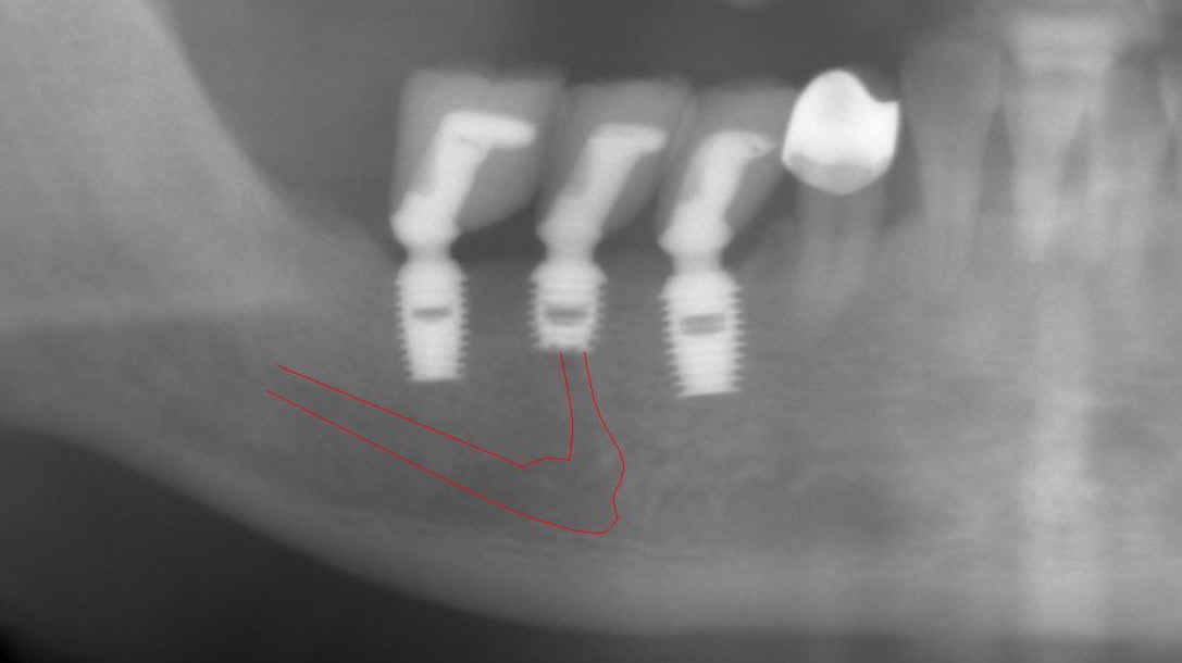 |
Fig.2 High looped mental nerve is noted
pre-op. To avoid potential damage to the nerve, local infiltration
was used. Flap was raised to expose the mental nerve before
osteotomy. A shorter implant was chosen for #29 (5x6mm), as compared
to 5x8 implants (Bicon) for #28 and 30. The depth of osteotomy for #29 was
controlled so as not to pass below the mental foramen, but still to bury
implant platform. According to manufacture manual, the implant
should be buried 2-3 mm below the ridge. No paresthesia was found
post-op, although #29 implant was apparently on the top of the mental nerve (red
tracing line). As shown below by cone-beam, the apex of this implant must be located
lingual to the mental nerve when the latter exits the mental foramen. The drawback is that a few of threads was exposed buccally
for #29 implant (not shown), probably because it was not buried deep
enough. The thread exposure was found during uncovering, 4
months after placement. No further treatment was pursued for thread
exposure. Integrated abutment crowns were placed for #28-30. This panorex
was taken 1.5 years after crown placement. Radiographically, implant
thread is below the alveolar ridge. Twenty eight
months since
functioning, these 3 implant-supported crowns have been stable with healthy
bone and gingiva. |
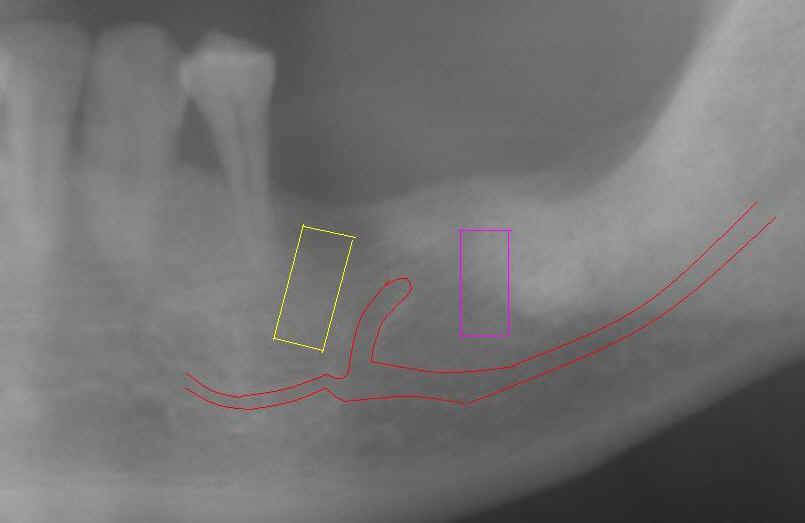 |
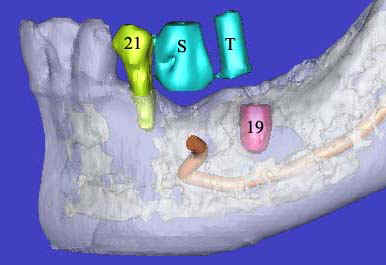
Fig.3 When the pan in Fig.2 was taken, the
patient requested more implants in the lower left quadrant. To
reduce thread exposure, we planned to place 2 implants (8 mm long) (#19 (pink tracing
line) and 20 (yellow) on the either side of the mental nerve and below the
ridge. These 2 implants should be above the inferior alveolar nerve
and incisive nerve, respectively. #20 implant should avoid touching
the neighboring root. An alternative was proposed to extract #21,
place implants at #19 and 21, and fabricate 3-unit fixed prosthetic
denture. The patient declined.
Notice the angulation of the implant for #20.
|
 |
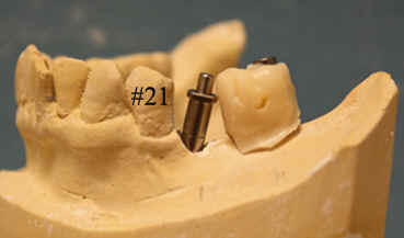 |
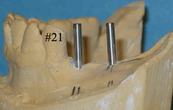
Fig.4 (left) and 5 (right) Model surgery
was performed to insert guiding rods for #19 and 20 (Fig.4). At that
time, it was thought that the implant #19 is more likely to invade the
mental nerve loop. It bends upward and distally. Effort was
made to design #19 osteotomy as distally as possible, as shown by the
metal tube inside acrylic in Fig.5. The tube exits at the distal
fossa of waxed-up tooth #19. Retrospectively, the angulation for #20 is not
correct (Fig.4). The axis
for #20 in Fig. 5 is more appropriate. A guiding tube was inserted
over a rod at #20. The rod and tube are purchased from Straumann. |
 |
 |
Fig.6 (left) and 7 (right) A PA was
taken immediately before implant placement (Fig.6). There are two radiolucent areas (including one being traced).
The surgeon did not see them or clearly realized that one of them is the
terminal part of the ascending mental nerve. If the sensor had been placed lower, the mental nerve
loop would have been more easily identified (Fig.7). The latter
X-ray was taken before 2nd surgery, which will be discussed below.
The message is that we should adopt paralleling technique (no tilting
or distortion) for X-ray and
insert the sensor or X-ray film as deep as possible when we place implant
around the lower premolars.
|
 |
 |
Fig.8 (left) and 9 (right) After initial
osteotomy, paralleling pins were inserted at 6 mm (Fig.8) and 8 mm
(Fig.9) for X-ray. The surgeon did not find the mental nerve relative
to the pins. He paid attention to changing the projectory of the pins/osteotomy
(compare Fig.8 vs. 9). The surgeon did not expose the mental nerve on
the left side.
As mentioned above, local infiltration was used during lower right
implant placement. In case the neural bundle is invaded, we may
notice it earlier. The drawback is that the depth of anesthesia
cannot be maintained for long. You have to re-inject
frequently. When working on the lower left quadrant, inferior
alveolar block was used from the beginning with local infiltration for
hemostasis. More importantly the mental nerve was not dissected for
orientation purpose.
|
 |
 |
Fig.10 (left) and Fig.11 (right)
Retrospectively we used a Windows Accessories Program called Paint to
trace the mental nerve and inferior alveolar nerve. At 6 and 8 mm of
osteotomy, the mental nerve may be violated. If the surgeon had been
more alert and had stopped the procedure or changed angulation,
paresthesia would have been avoided or much less. At the upper
level, the mental nerve inside the mandible is buccal to the osteotomy
(which will be discussed below). The subtle sign of invading the
inferior alveolar neurovascular bundle is that there is more oozing from
the osteotomy of #20 than #19. There is no sudden breakthrough
during osteotomy. |
 |
 |
Fig.12 and 13 Since the
surgeon failed to notice the relationship of initial osteotomy to the
mental nerve, he kept increasing osteotomy depth (to ~11 mm below the
alveolar ridge) and diameter to 4.5 mm for #20 and 5.0 mm for #19.
After the patient left, he reviewed post-op X-ray and noticed that #20 implant
pinched the inferior alveolar nerve (Fig.11).
Tracing further shows that the implant overlaps the mental nerve
(Fig.12). Paresthesia was found in the left lower lip and
teeth. The extent of parethesia of the lip and chin was
recorded. The offending implant was removed on the 3rd day
post-op. Paresthesia decreased 4 weeks later and completely resolved
by 2 months. Another 4 months later, the patient returned for #20
implant placement for the second time. A new pre-op PA was taken
again immediately before the scheduled surgery. The high position of
the mental nerve appears to wake up the doctor for the first time. The
alternative (extracting #21, placing an implant on #21, using both #19 and
21 implants as abutments for fixed work) was proposed again. The
patient did not accept it. The surgery was canceled. Since #19
implant was placed relatively too distally, it would be inappropriate to use
to use it to make a cantilever fixed prosthesis. An implant should
be placed in the narrow space between the mental nerve and #21 root
(Fig.7). The angulation was designed in Fig. 3 and 5. Surgical
stent was fabricated after placing orientation rod and tube (Fig.5) before
cone beam. |
 |
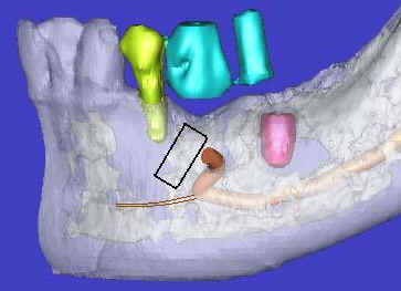 |
Fig. 14 and 15 Cone beam confirms the
close relationship between the mental nerve and the root of the tooth
#21. S: stent with barium sulfate for #20 implant placement; T: tube
inside acrylic without barium sulfate for previous placement of #19 implant. Please note that as the
mental nerve loops ascends, it is more buccally located. It is more likely to injury the mental nerve as osteotomy goes deep.
Osteotomy tends to be in the middle of the bone. It is imperative to
tilt the osteotomy as shown by simulation of implant placement (black
rectangle in Fig.15). The osteotomy should also avoid injuring the
incisive nerve (brown lines). Although cone beam provides tremendous
information, the operator depends heavily upon routine X-ray during
implant placement. He needs several quality intra-op X-ray to adjust the angulation
and position of the osteotomy as shown below. |
 |
 |
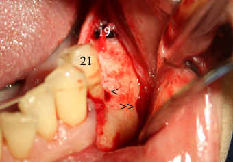
Fig.16 and 17 First of all, make an incision and
raise the flap to expose the mental nerve (double arrowheads in
Fig.16). Use this and neighboring landmarks (the tooth #21 and
healing plug of implant #19) to make an initial osteotomy (single
arrowhead). Insert a paralleling pin and take PA (Fig.17). Notice
the angulation as compared to that in Fig. 8 and 9. The osteotomy
needs to move distally using side-cutting bur: Lindemann (Brasseler). |
 |
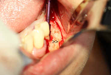 |
Fig.18 and 19 The position of the
osteotomy appears to be more appropriate (Fig.18). Always be alert
during any step of osteotomy. Direct your bur (the tip more exactly,
Fig.19) away from the mental
nerve at the foramen and particularly below (mentally). Initially local
infiltration was adopted. Intra-op, the patient reported pain.
At that moment, the depth and angulation of osteotomy had been decided to
be safe and sound. Pain was also determined not from the area close
to the mental nerve within the mandible while a reamer (bur) was turning. Then block anesthesia was
performed. |
 |
 |
Fig.20 and 21 These two X-ray images were
taken immediately after pressing
in a 4.5x8 Bicon implant. Before implant insertion, surgical curet
was used to remove bone shaving from osteotomy site and gently explore the wall of
the osteotomy next to the mental nerve. It was felt that there is no
perforation. The patient reported minimal numbness post-op. Exposure and stretching the mental
nerve during procedure may contribute to this type of minor nerve injury.
Retrospectively, the implant could have been smaller in diameter: 4.0 or 3.5
mm. Restoratively these two implants should be splinted due to
the angulation discrepancy. |
| |
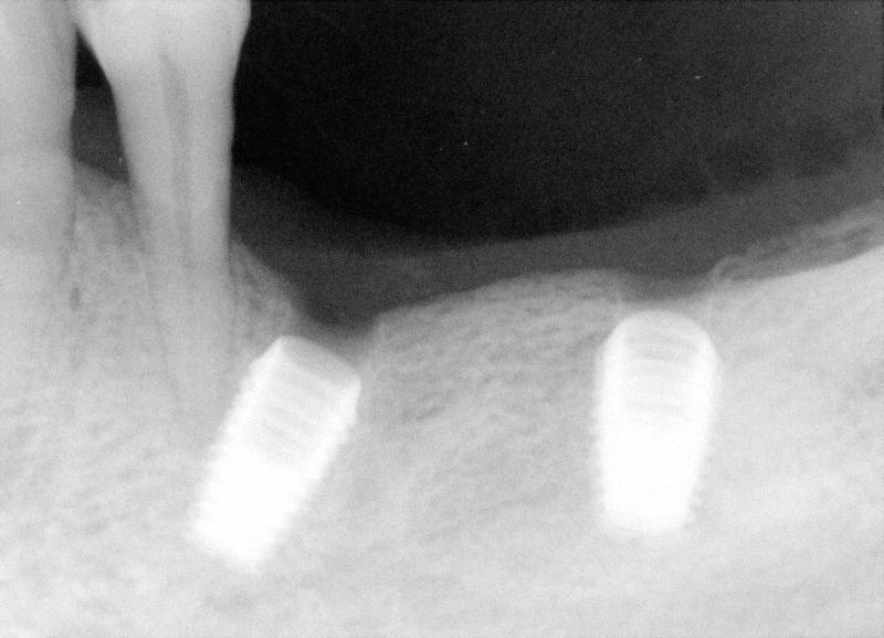 |
Fig.22 This PA was taken 14 months after #20
implant placement (2nd time). Two months later, final restorations were placed. |
The author has not obtained any financial support from outside. But he
is very grateful for receiving advice from Dr. Craig Schille in this case.