|
|
|
|
|
|
|
|
|
|
|
|
|
|
|
|
Use of Endo X-ray Device to Reduce the Chance of Inferior Alveolar Nerve Injury During Lower Posterior Implant Placement
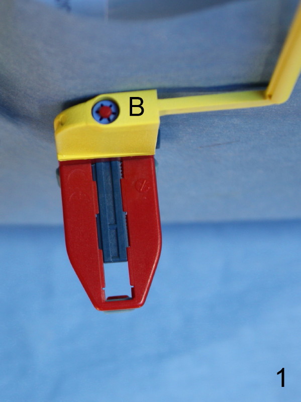
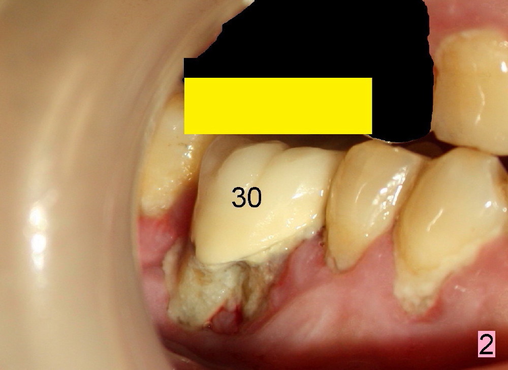
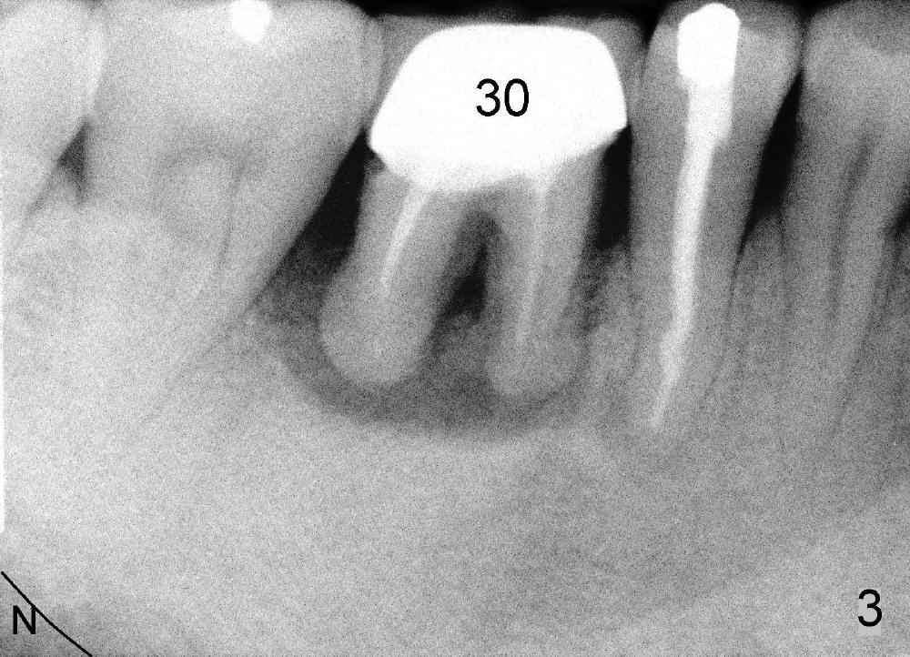
Regular posterior periapical (PA) device has a horizontal bite block (Fig.1: B). The latter rests on the occlusal surface of the posterior teeth to be taken radigraphically (Fig.2 illustration: yellow rectangle). This typical PA image shows the whole teeth including the crowns and the roots, but it does not catch the whole image of the inferior alveolar nerve as related to implant placement (Fig.3 N). The tooth #30 has complex endo-perio disease and is going to be extracted and restored by an implant.
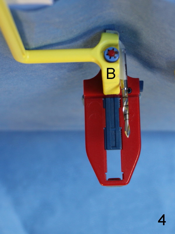
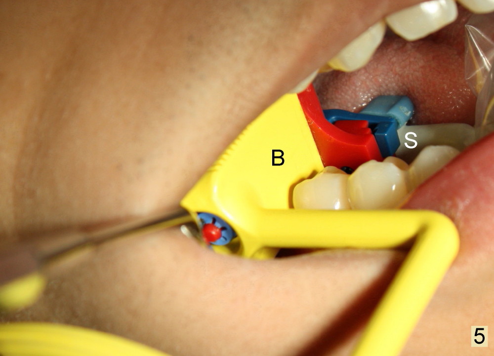
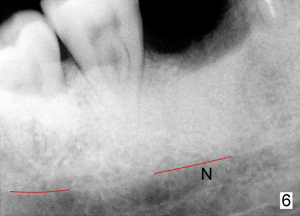
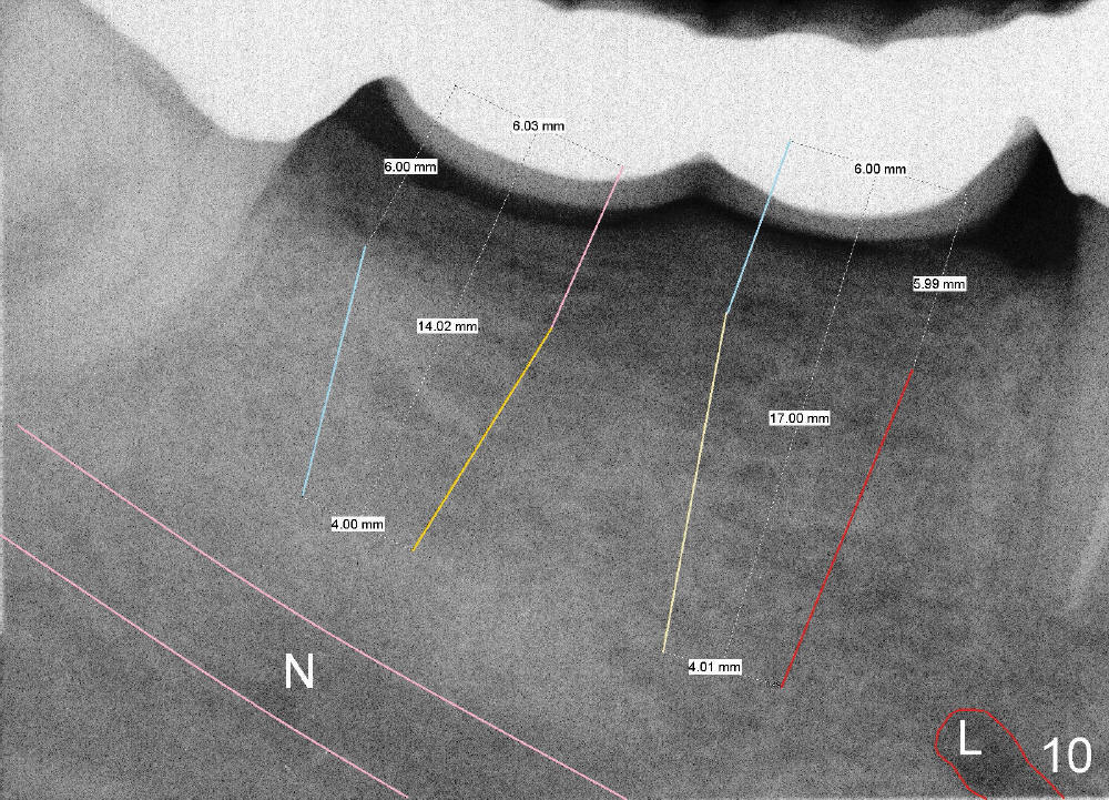
In contrast, the bite block of an endo X-ray device is vertical and narrow mesiodistally (Fig.4: B, as compared to Fig.1). It can be inserted into the edentulous space after extraction (Fig.5: B); the sensor (S) is placed deeply into the lingual vestibule. The corresponding PA does not show the coronal portions of crowns and roots next to the edentulous area (Fig.6), but it shows the the inferior alveolar nerve (N). It would be the best to measure the bone height and do treatment planning on the image as will be shown in Fig.10), since the endo device may not be inserted deep enough intraoperatively as shown below.
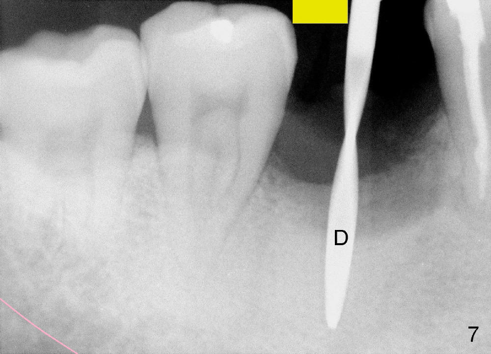
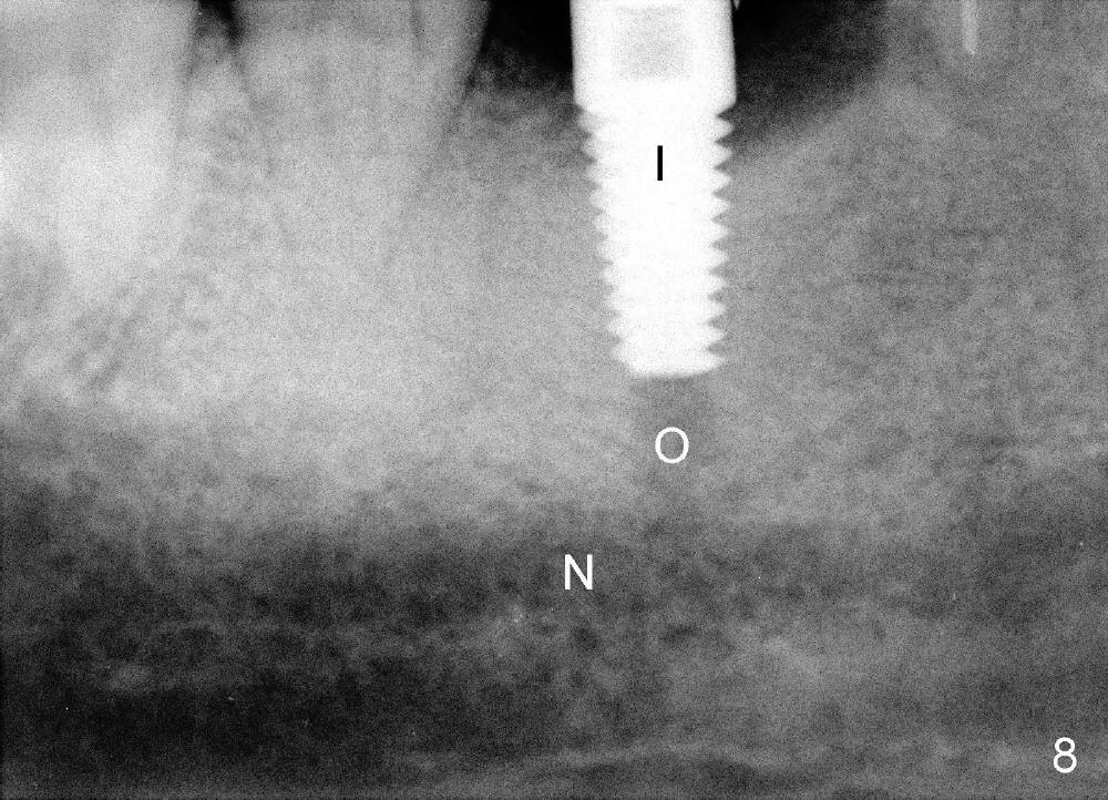
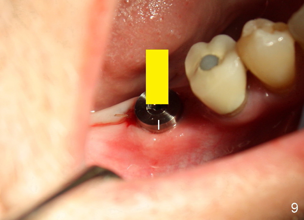
When the pilot drill is inserted into the initial osteotomy site for X-ray confirmation of its depth (Fig.7: D), the vertical block of the endo device (yellow rectangle) may be blocked due to the narrow divided edentulous space. The crown of the molar is shown, whereas the inferior alveolar nerve is not shown except a small portion in the left lower corner of Fig.7 (pink line). The depth of the further osteotomy (Fig.8: O) was chosen without accurate estimate. The integrity of the inferior alveolar canal (IAC) was violated, although the implant (I) was not placed that deep. The patient experienced transient postop pain, which was controlled by Medrol Dosepak. A correct way to prevent iatrogenic neuropathy in this situation is to remove the pilot drill, and place the endo device as deep as possible. The new X-ray should be able to reveal the relationship of the end of the osteotomy (shadow) to IAC. Measurement must be done using digital X-ray software over the new image to determine how deep osteotomy should be made (as shown in Fig.10). When an implant is placed (I in Fig.9: a second case as will be shown in Fig.10-12), the vertical block of the endo device can be placed on the implant. The sensor is placed deep into the lingual vestibule to show IAC in relation to the implant (Fig.8).
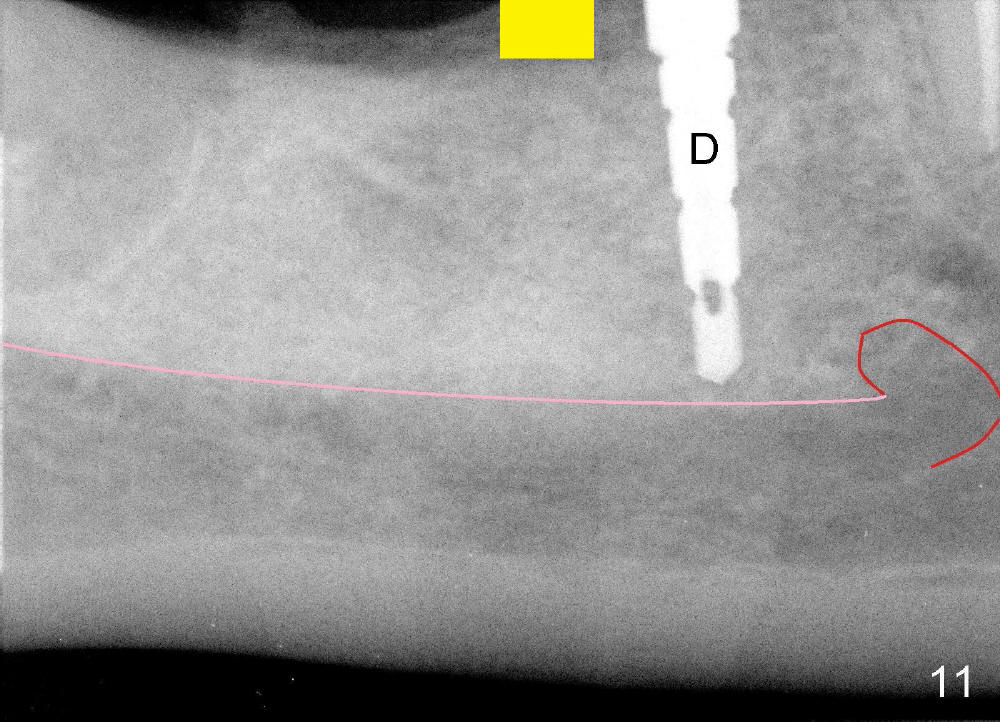
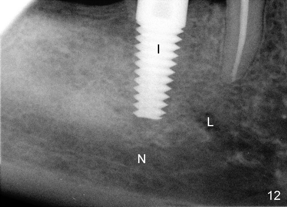
Sometimes the regular X-ray device may show part of IAC and mental nerve loop (Fig.10: N, L). In this case, the abutment tooth #32 is extracted due to caries and infection, after sectioning between #29 retainer and #30 pontic. Two implants are planned to be placed at the sites of #30 and 31. Treatment plan is done preoperatively. The length and diameter of the implants are determined preliminarily (6x17 and 6x14 mm, respectively). The vertical block of the endo device (Fig. 11: yellow rectangle) is easily placed next to a drill (D) because of ample edentulous space. Therefore, the implant (Fig.12: I, 6x17 mm as planned) is placed smoothly without encroaching the nerve (N) or loop (L). In summary, do not make osteotomy without identifying radiographic anatomy or doing accurate preop or intraop measurement. With proper usage of the endo X-ray device, we can safely place implants in the mandibular posterior region. Return to Professionals
Xin Wei, DDS, PhD, MS 1st edition 12/05/2012, last revision 12/09/2012